
Engineering Guide / Closure Architecture Comparison
Continuous vs Segmented Magnetic Zipper Strip
A technical designer's framework for choosing between extruded continuous magnetic compound and enclosed segmented magnet constructions across apparel plackets, technical gear, and sealed pouch openings.
OEM components · matched A/B constructions · project-specific review
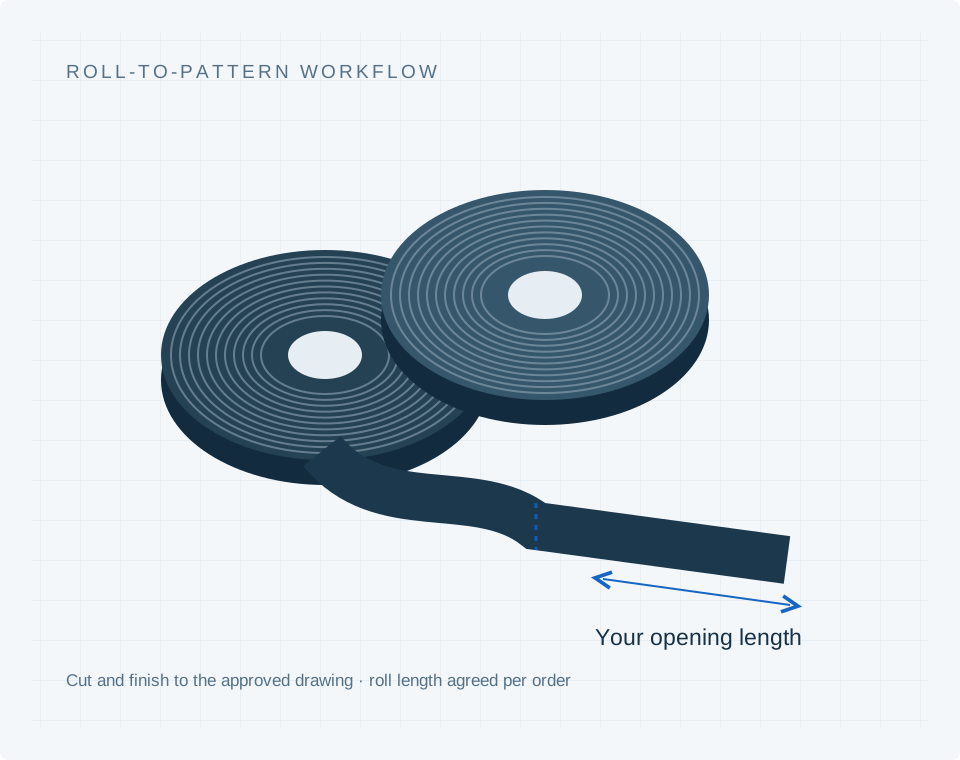
A closer material comparison
Different formats. Different integration questions.
Look at the supplied form as well as the closure concept. Raw stock, enclosed strips and individual packets have different interfaces.
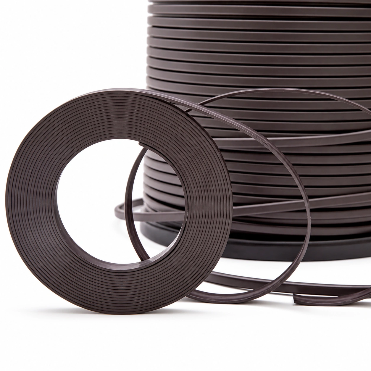 Material reference
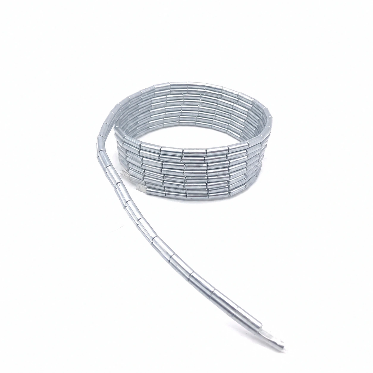 Component reference
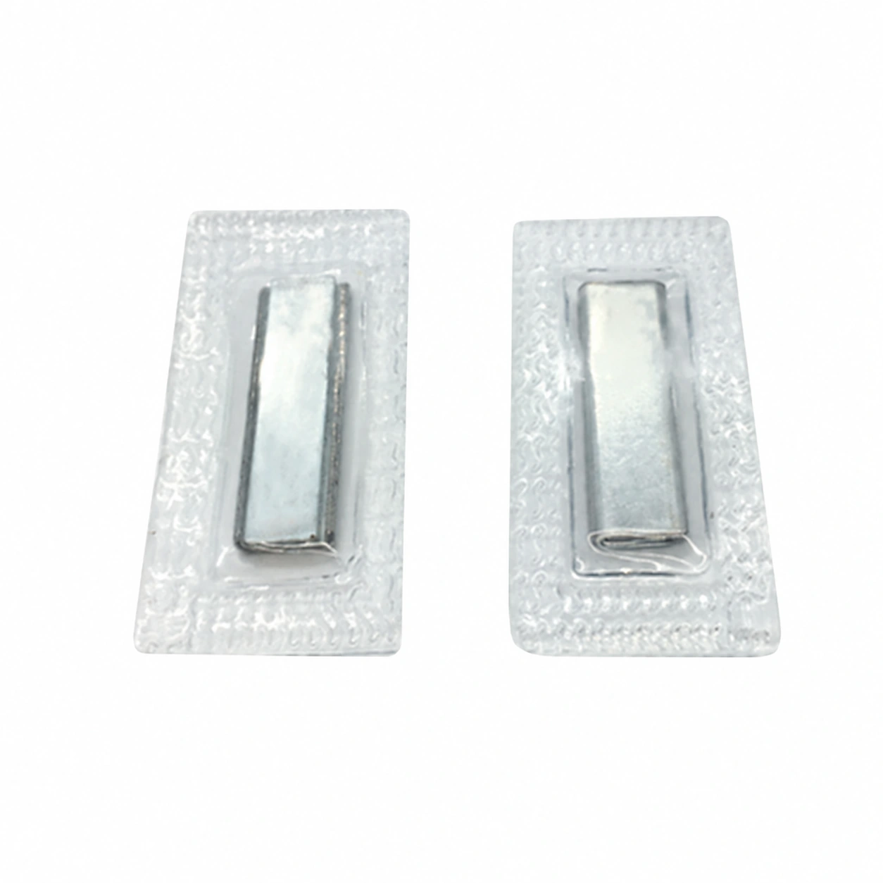 Component reference
Prepared material, component and application references. The selected construction and finished specifications are confirmed for your project.
01 / Architectural Dichotomy
Two Distinct Physical Paradigms for Toothless Magnetic Closures
When technical designers eliminate slider-driven zipper coils in favor of self-aligning magnetic seams, they face a foundational materials and kinematic decision: extrude a continuous magnetic compound strip or encapsulate discrete, rigid magnetic segments inside an articulated sleeve.
This is not merely a supplier sourcing nuance. It dictates minimum bending radius, seam drape, automated cutting flexibility, terminal retention engineering, thermal limits during pressing, and factory sewing machine configurations.
Option A: Continuous Magnetic Compound
Formulated by blending fine strontium/barium ferrite or bonded rare-earth magnetic powder into a synthetic elastomer matrix (CPE, EPDM, or TPU). Multi-pole magnetized along alternating surface tracks.
- Continuous 1.0 mm cut resolution with standard guillotine knife
- Smooth 2D curvature without visible faceting or hard lumps
- Uninterrupted contact surface for air and liquid barrier seals
- Uniform tactile opening force across the entire placket span
- Lower clamp per cm²; requires close textile interface gap (< 0.6 mm)
- Rapid stray field decay (< 22 mm to 5 Gauss medical safe limit)
Option B: Enclosed Segmented Cord
Constructed with discrete, high-energy sintered NdFeB (N35–N52) or ceramic blocks enclosed at pitched intervals within a heat-sealed TPU tube or woven textile channel.
- High localized clamp (8–25 N per node) through thick garment stacks
- Polygonal chain articulation allows sharp 3D garment draping (R < 3 mm)
- Cutting strictly constrained to empty inter-element textile webs
- Rigid segments (15–25 mm) resist in-plane lateral shear slipping
- Requires dedicated terminal pinch sealing or bartack anchoring
- Extended stray field (~75 mm to 5 Gauss); requires FDA 15 cm safe clearance
02 / Interface Geometry
Cross-Section Analysis & Needle Clearance Margins
Seam failure almost always originates at the needle puncture margin. Sewing needles must never strike or penetrate a hard magnetic core. Reviewing the cross-sectional geometry establishes safe manufacturing clearance before garment patterns are finalized.
| Parameter / Property | Continuous Extruded Strip (MZS-FlexTape™) | Enclosed Segmented Cord (MZS-Cord™) |
|---|---|---|
| Core Material System | Isotropic/Anisotropic Ferrite or Bonded Rare-Earth in Polymer Binder | Sintered Neodymium Iron Boron (NdFeB N35–N52) or Sintered Ferrite |
| Encapsulation / Carrier | Woven polyester textile flange, co-extruded TPU edge, or hot-melt adhesive film | RF-welded TPU tubular sleeve, woven piping channel, or sonically welded pockets |
| Core Thickness Profile | 1.0 mm to 2.2 mm (low-profile seamless silhouette) | 2.5 mm to 4.5 mm (accommodates block height and protective walls) |
| Total Strip Width | 12.0 mm to 20.0 mm including stitch carrier flange | 14.0 mm to 24.0 mm including side fabric seam allowance |
| Approved Needle Margin | ≥ 4.0 mm from magnetic core outer boundary | ≥ 5.0 mm clear of rigid magnet block sidewall |
| Finished Weight (approx.) | 45 g/m to 85 g/m (ferrite); 65 g/m to 120 g/m (bonded NdFeB) | 90 g/m to 160 g/m (sintered blocks + sleeve assembly) |
03 / Kinematics & Mechanics
Bending Radii, Fabric Gaps & Magnetic Flux Continuity
How a closure bends determines whether a garment drapes naturally on the human body or behaves like a rigid splint. Furthermore, because magnetic force diminishes dramatically across non-magnetic air gaps, flexural deformation directly impacts closure security.
| Kinematic Characteristic | Continuous Magnetic Tape | Segmented Enclosed Cord | Engineering Significance |
|---|---|---|---|
| Minimum Bending Radius (R_min) | 12 mm – 25 mm (2D in-plane bend) | < 3 mm (at flexible hinge node) | Segmented cord executes acute corner turns without puckering. |
| 3D Compound Contour Drape | Moderate; resists torsional twist along compound body curvatures | Superior; flexible textile webs twist up to 90° in multi-axis motion | Segmented structures conform to articulated shoulder/elbow seams. |
| Faceting & Visual Lumpiness | Zero faceting; completely smooth uninterrupted silhouette | Faceted profile; rigid blocks form straight polygon chords under tension | Continuous tape is preferred for fine fashion and clean tailored plackets. |
| Flux Bridge Across Gaps | Unbroken continuous linear flux bridge across seam line | Zero-flux voids (8–15 mm) between active magnetic blocks | Continuous tape prevents dust, wind, and splash infiltration. |
| Force Retention at 1.0 mm Fabric Gap | 35% – 45% of nominal contact holding force | 60% – 75% of nominal contact holding force (high remanence Br) | Segmented NdFeB is required when penetrating heavy outer shell + fleece lining. |
04 / Thermodynamic Reliability
Thermal Demagnetization Limits, Steam Ironing & Laundering Resistance
Permanent magnets are not universally heat-tolerant. During garment manufacturing (hot-head pressing, steam tunnel finishing, seam tape welding) and consumer care (laundering, tumble drying), closures face severe thermal stress. Selecting incorrect magnetic grades results in irreversible thermal demagnetization, where holding force permanently degrades.
The critical temperature at which magnetic order completely vanishes. Ferrite Tc ≈ 450°C; Sintered NdFeB Tc ≈ 310°C–340°C. Structural polymer binders (TPU/CPE) degrade well before Curie thresholds are reached.
Standard commercial N35–N52 grade NdFeB loses magnetic orientation permanently above 80°C. Garments undergoing commercial steam pressing (130°C–150°C) require specialized SH (150°C) or UH (180°C) grades.
Under 50 domestic wash cycles at 40°C (Program 4N + tumble dry), both continuous ferrite and nickel-plated NdFeB encased in sealed TPU exhibit < 4% reversible flux drift and zero rust bleed.
| Magnetic Material Grade | Curie Temp (Tc) | Max Continuous Operating (Tw) | Irreversible Loss Threshold | Process Compatibility & Limits |
|---|---|---|---|---|
| Polymer-Bonded Ferrite (MZS-FlexTape™) | ~450°C | 80°C (binder limited) | > 95°C (binder softening occurs) | Safe for 40°C–60°C domestic wash; limit steam iron contact to < 100°C with press cloth. |
| Standard Sintered NdFeB (N35 / N45) | ~310°C | 80°C | > 85°C (15%–40% permanent loss) | Not recommended for industrial tunnel finishers or hot-head presses (130°C–160°C). |
| High-Temp Sintered NdFeB (N38SH) | ~340°C | 150°C | > 155°C | Approved for commercial steam pressing (130°C–145°C) and hot-air seam taping. |
| Ultra-High Sintered NdFeB (N35UH) | ~350°C | 180°C | > 185°C | Required for direct RF membrane welding and high-temperature autoclave processes. |
05 / Compliance & Proximity Safety
Stray Magnetic Fields, Pacemaker Safe Distances & IATA Air Logistics
Permanent magnetic closures emit static magnetic fields into surrounding space. Technical designers must engineer against two major regulatory risks: interference with active implantable medical devices (such as cardiac pacemakers and ICDs) and aviation safety regulations for air cargo (IATA Dangerous Goods Regulations PI 953).
Active medical implants like cardiac pacemakers and ICDs incorporate magnetic reed switches or Hall sensors designed to activate "Magnet Mode" (asynchronous pacing or therapy suspension) when exposed to fields exceeding 5 Gauss (0.5 mT).
- Continuous Multipolar Tape: Alternating multi-pole orientation causes magnetic field lines to loop tightly between adjacent tracks. Flux decays rapidly and drops below 5 Gauss within < 22 mm from the strip face.
- Segmented Sintered NdFeB Cord: Discrete high-remanence blocks produce open dipole fields that exceed 5 Gauss up to 75 mm away.
- Design Rule: Segmented NdFeB closures must never be specified in left chest plackets or upper breast pockets. Maintain at least 150 mm (6 inches)clearance from pacemaker pulse generators as recommended by FDA/AHA guidelines.
Air transport of magnetized materials (UN 2807) is governed by strict stray flux limits to prevent interference with aircraft magnetic compasses and avionics navigation instruments.
- Class 9 Regulated Threshold: Consignments producing > 0.00525 Gauss (5.25 milligauss / 0.418 A/m) or > 2° compass deflection at 4.6 meters (15 feet)are classified as Dangerous Goods and require special approval.
- Non-Restricted Exemption Limit: Shipments producing < 0.002 Gauss (2.0 milligauss) at 2.1 meters (7 feet) qualify as ordinary non-hazardous air freight.
- Factory Packaging SOP: Continuous tape naturally self-shields when spooled face-to-face. Segmented NdFeB rolls must be wound in matched pairs and packaged in cartons lined with 0.5 mm galvanized steel flux-keeper sheets to ensure unhindered global air shipping.
06 / Manufacturing Dynamics
Axial Alignment Tolerance & Differential Sewing Drift Sensitivity
On high-speed factory sewing lines, differential fabric feed between the upper and lower placket plies is an everyday manufacturing reality. How each closure architecture tolerates longitudinal sewing drift (ΔX) dictates factory rejection rates and operator skill thresholds.
| Axial Drift Offset (ΔX) | Continuous Extruded Strip (MZS-FlexTape™) | Segmented Enclosed Cord (MZS-Cord™, 25 mm Block / 10 mm Gap) | Assembly Consequence |
|---|---|---|---|
| ΔX = 0 mm (Nominal) | 100% nominal linear holding force | 100% nominal clamp force (full block overlap) | Ideal factory baseline under precision alignment fixtures. |
| ΔX = 5 mm (Minor Drift) | 100% force retained (infinite longitudinal continuity) | 80% force retained (active overlap reduced to 20 mm) | Continuous tape unaffected; segmented cord experiences slight corner shear pull. |
| ΔX = 12 mm (Moderate Drift) | 100% force retained; zero puckering | 52% force retained; angular magnetic shear begins to distort seam | Segmented cord causes visible placket skewing and uneven drape. |
| ΔX = 20 mm (Critical Drift) | 100% force retained; zero placket puckering | Severe failure: magnet block aligns with opposing empty web or next block edge | Segmented closure exhibits severe placket gaping, puckering, and rejection. |
07 / Defect Root Cause Analysis
Common Engineering Failure Anti-Patterns & Prevention Protocols
Prototypes often fail not because the magnetic closure was defective, but because the wrong architecture was forced into an incompatible physical environment. Review these four documented failure anti-patterns to avoid costly tooling re-spins.
Symptom: Continuous magnetic tape installed along an acute curved pocket flap (radius R < 25 mm) pops open spontaneously at the apex.
Root Cause: Bending a solid elastomer strip in-plane creates tensile stress on the convex outer margin and compressive puckering on the concave inner edge. The elastic restoring torque exceeds the magnetic clamp of flexible ferrite, causing progressive peel failure.
Corrective Action: Switch to segmented cord with flexible unmagnetized textile hinges positioned exactly at the apex of the curve.
Symptom: Broken sewing machine needles, chipped cutting blades, and spool contamination with powdery black magnetic debris.
Root Cause: Operators sewing without guide gauges allowed the needle to wander into the rigid NdFeB magnet block instead of staying on the lateral carrier flange. Sintered rare-earth alloys have zero ductility; needle impact fractures the nickel barrier and pulverizes the core.
Corrective Action: Install mechanical edge-guide fences ensuring a strict ≥ 5.0 mm stitch clearance margin clear of the magnet envelope.
Symptom: Jacket front placket snaps shut firmly in sampling, but feels weak and sloppy after exiting final garment steam finishing.
Root Cause: Standard N35 grade NdFeB magnets (maximum operating temperature 80°C) were subjected to commercial buck pressing at 145°C for 15 seconds, causing permanent irreversible flux loss exceeding 40%.
Corrective Action: Specify N38SH grade sintered magnets (rated to 150°C) or instruct the finishing floor to bypass direct hot-head pressing over magnetic plackets.
Symptom: After 5 home washing cycles, the top magnet of a segmented cord migrated out of position and broke through the garment shoulder seam.
Root Cause: The factory cut the segmented cord at the web hinge but relied solely on a single standard row of sewing thread to close the end channel. Centrifugal force during 1200 RPM spin cycles forced the end magnet through the seam.
Corrective Action: Implement an ultrasonic pinch weld or a high-density 42-stitch reinforced bartack terminal stop behind the final element.
08 / Cut-To-Length Logistics
Permitted Cut Positions & Production Sizing Flexibility
Apparel grading requires sizing increments across XS to 3XL ranges. How each architecture accommodates cut-to-length logistics governs factory scrap, tooling lead times, and inventory complexity.
| Cutting Specification | Continuous Extruded Tape | Segmented Enclosed Cord |
|---|---|---|
| Permitted Cut Locations | 100% of length span. Cut anywhere at 1.0 mm resolution. | Restricted strictly to empty inter-element textile hinges. |
| Pitch Constraint | None (infinitely variable cut-to-order length) | Fixed Pitch P = L_magnet + L_hinge (e.g. 25 mm + 10 mm = 35 mm) |
| Tooling Required | Standard rotary guillotine or textile shear blades | Optical or mechanical gap sensor on automatic cut-and-feed stations |
| Blade Damage Risk | Zero risk; polymer compound slices like heavy vinyl | Critical risk; blade strike on NdFeB shatters magnet and chips blade |
| Production Scrap Rate | Negligible (< 1.5% off-cut trim loss) | 5% to 15% if garment pattern length does not match pitch multiple |
| Pattern Grading Compatibility | Fully compatible with 10 mm and 15 mm standard apparel grade rules | Requires pattern adjustments to match integer segment counts |
09 / Terminal Engineering
End Retention & Terminal Sealing Methods
When a user peels open a magnetic closure, mechanical stress peaks at the initial separation node. Without engineered end retention, cut ends fray, internal magnets migrate under shear, and raw compound edges can degrade in commercial washing cycles.
| Method | Process & Equipment | Pull-Out Retention | Water Ingress Protection | Best Fit Application |
|---|---|---|---|---|
| 1. Ultrasonic Pinch Weld | Ultrasonic sonotrode/anvil (20–35 kHz) collapses TPU sleeve behind last element | > 90 N terminal pull resistance | Hermetic seal; resists IPX7 immersion | Technical dry bags, welded pouches, marine outerwear |
| 2. High-Density Bartack | 42-stitch bar tack in non-magnetic web hinge using non-ferrous needle plate | > 120 N mechanical fabric retention | Porous; relies on outer fabric DWR | Workwear, tactical jackets, heavy plackets |
| 3. Molded End-Cap Plug | Sonic-welded or mechanically crimped nylon/TPU terminal cap | > 70 N clamp retention | Splash-resistant (gasketed fit) | Luggage openings, camera bag flaps, visible trims |
| 4. Fold-Over Placket Wrap | Outer fabric turned back 15 mm and secured with perimeter box-X stitching | > 100 N fabric-limited retention | Dependent on shell membrane | Clean tailored apparel, concealed plackets |
10 / Original Deliverable
Core Architecture and Processing Decision Matrix
Use this multi-variable engineering matrix to systematically determine whether your project requirements mandate Continuous Compound Tape (MZS-FlexTape™) or Enclosed Segmented Cord (MZS-Cord™), alongside the mandatory factory processing route.
| Design / Operating Parameter | Threshold / Requirement | Recommended Architecture | Factory Processing Route |
|---|---|---|---|
| Target Shear Retention (High Load > 15 N) | High (> 15 N/node load; loaded pockets/bags) | Segmented Enclosed NdFeB Cord | Flange stitch with reinforced 42-stitch bartack stops at both terminals. |
| Target Shear Retention (Low/Moderate < 6 N) | Low to Moderate (< 6 N/cm; storm flaps, adaptive plackets) | Continuous Magnetic Flexible Tape | Standard lockstitch along textile carrier margin with Teflon presser foot. |
| Seam Curvature (Compound 3D / Saddle) | Compound 3D saddle curve, elbow or shoulder articulation (R < 15 mm) | Segmented Enclosed Cord | Assemble with flexible web hinges placed exactly at pattern flex apexes. |
| Seam Curvature (Gentle 2D / Straight) | Straight placket or gentle 2D curve (R > 35 mm) | Continuous Flexible Tape | Differential feed calibration (0.9 ratio) to prevent placket puckering. |
| Sizing Grading (Arbitrary Non-Standard) | Arbitrary non-standard lengths (e.g. 237 mm, 312 mm) | Continuous Flexible Tape | Direct guillotine automated cut-to-length; zero scrap pitch rounding. |
| Sizing Grading (Fixed Integer Pitches) | Pre-engineered fixed standard lengths (multiples of 35 mm) | Segmented Enclosed Cord | Optical sensor indexing cut line strictly in center of 10 mm web gap. |
| Environmental Barrier | Continuous wind, dust, or water barrier without gap voids | Continuous Flexible Tape (TPU weldable) | RF or hot-air membrane welding at 160°C–180°C directly to bag film. |
| Heavy Insulation Stack | Compressed fabric stack > 1.2 mm between opposing strips | Segmented Sintered NdFeB Cord | Specifies N45/N52 grade cores to project flux across thick fleece/down layers. |
| Medical Proximity (Chest Pocket) | Located < 150 mm from heart / cardiac pacemaker implantation site | Continuous Multipolar Flexible Tape | Multipolar closed flux paths reduce field to < 5 Gauss within 22 mm safe boundary. |
| Finishing Heat Exposure | Industrial steam pressing / buck press > 130°C | High-Coercivity Segmented Cord (SH/UH Grade) | Must specify N38SH (150°C) or N35UH (180°C) to prevent irreversible thermal loss. |
11 / Engineering Case Studies
Labelled Illustrative Worked Cases
The following engineering scenarios demonstrate how the decision matrix is applied across diverse product categories. Note: All numeric values, clamp targets, and process parameters are illustrative worked engineering baselines for prototyping review, not certified catalog guarantees.
Weatherproof Technical Shell Storm Flap
Application: Front storm flap covering central water-resistant coil zipper.
Baseline Opening: 720 mm straight vertical placket.
Fabric Stack: 3-layer 70D nylon ripstop with PTFE membrane (compressed stack = 0.55 mm per side, total magnetic gap = 1.10 mm).
Architecture Choice: Segmented Enclosed NdFeB Cord (MZS-Cord™).
Rationale: Wind buffeting on mountain shells generates high peel flutter. Continuous ferrite at 1.10 mm air gap lacked sufficient clamp. 18 sintered N40 NdFeB blocks (20 × 6 × 2.5 mm) at 40 mm pitch deliver 14 N localized snap.
Terminal Detail: Sealed TPU sleeve with 42-stitch bartack in fabric hem.
Failure Criterion: No flap separation at 60 km/h simulated wind blast.
Adaptive Childrenswear Magnetic Shirt Placket
Application: Assisted-dressing front closure disguised as standard button placket.
Baseline Opening: 440 mm shirt front, standard 100% cotton poplin.
Fabric Stack: 2 plies of 120 g/m² cotton (compressed stack = 0.30 mm, total magnetic gap = 0.60 mm).
Architecture Choice: Continuous Flexible Ferrite Tape (MZS-FlexTape™).
Rationale: Discrete blocks produced visible rigid ridges and uncomfortable pressure points when seated. Continuous tape (12 × 1.2 mm) creates a fluid, natural drape that mimics conventional sewn plackets with gentle 2.2 N peel opening force. Multipolar closed field falls below 5 Gauss within 22 mm, ensuring safe clearance from pediatric cardiac implants.
Terminal Detail: Top and bottom folded collar/hem envelope stitched clear of core.
Failure Criterion: Zero core cracking after 50 wash cycles at 40°C (ISO 6330).
Tactical Backpack Quick-Access Top Flap
Application: Glove-operated silent access lid over internal radio pocket.
Baseline Opening: 280 mm curved lid edge (radius R = 45 mm at corners).
Fabric Stack: 500D Cordura laminated to 2 mm closed-cell EVA foam (total gap = 2.4 mm).
Architecture Choice: Segmented Enclosed Sintered NdFeB (N48 grade).
Rationale: Heavy foam insulation requires intense flux penetration. Corner curve requires inter-element hinge flex. 7 high-power NdFeB blocks with nylon pull-tab allow fast peel while resisting accidental bag drop loads.
Terminal Detail: Hypalon end reinforcement with boxed-X stitch stop.
Failure Criterion: Flap remains closed during 1.2 m loaded drop test.
RF-Welded Roll-Top Waterproof Pouch Opening
Application: Self-closing magnetic guide lip on dry-bag opening before rolling.
Baseline Opening: 340 mm straight pouch mouth, 420D TPU-coated nylon.
Fabric Stack: Single TPU film layer (0.25 mm) directly welded over strip.
Architecture Choice: Continuous Co-Extruded TPU Magnetic Strip.
Rationale: A segmented cord creates periodic gaps where water droplets enter during folding. Continuous strip provides an unbroken self-aligning lip that snaps shut evenly across all 340 mm before the user initiates roll folds.
Terminal Detail: High-frequency RF weld sealing strip ends into perimeter pouch seams.
Failure Criterion: Complete edge alignment without operator intervention.
12 / Manufacturing Readiness
Factory Floor Assembly Evidence & Equipment Retrofits
Transitioning magnetic closure strips from sample prototypes to high-speed sewing lines requires disciplined workstation controls. Because permanent magnets attract ferrous tooling, assembly floors must implement non-magnetic retrofits.
| Workstation Element | Standard Sewing Line Setup | Magnetic Strip Conversion Requirement | Process Safeguard |
|---|---|---|---|
| Throat Plate / Bed | Hardened carbon steel | Replace with Solid Brass or 7075-Alloy plate | Eliminates magnetic bed drag and bunching. |
| Presser Foot | Standard steel double-toe foot | Teflon-coated or Delrin narrow zipper foot | Prevents foot attraction and provides needle margin. |
| Feed Dogs | Aggressive steel teeth | Fine-tooth rubberized or polished non-ferrous | Calibrate feed differential to avoid fabric puckering. |
| Needle Selection | Standard round point chrome needle | Ballpoint (SES) titanium-nitride coated needle | Reduces friction and prevents carrier weave damage. |
| Operator Hand Tools | Steel tweezers and snips | Non-magnetic titanium, brass, or plastic tweezers | Prevents magnetic strip from jumping to operator tools. |
| Inspection Gate | Verification Parameter | Method & Tolerance | Disposition on Failure |
|---|---|---|---|
| IQC 1: Polarity Pairing | Side A and Side B magnetic orientation | Check against calibrated polarity sensor or master pair template | Reject spool batch if repulsion or polarity reversal detected. |
| IQC 2: Core Continuity | Absence of internal cracked segments | Visual light table or eddy current scan along strip length | Quarantine spool if cracked NdFeB blocks detected. |
| IPQC 1: Cut Offset | Segmented cord cut location in web hinge | Optical caliper check: cut must be centered within ± 2.0 mm of web | Adjust optical feeder sensor if cut enters magnet buffer zone. |
| IPQC 2: Stitch Clearance | Distance between seam line and magnetic core | Gauge template inspection: needle line ≥ 4.0 mm clear of core | Halt line if needle punctures core or rubs protective sleeve. |
| OQC 1: Terminal Retention | Pull force of ultrasonic or bartack stop | Destructive sample test: terminal must withstand > 90 N pull | Recalibrate ultrasonic weld time/energy if weld delaminates. |
13 / Reliability & Testing
Testing Protocols, Standards & Evidence Limitations
Magnetic closure strips operate under combined shear, peel, environmental, and laundering forces. To prevent field failures, design teams must qualify assemblies using reproducible engineering test methods rather than subjective hand-feel.
| Performance Test | Applicable Standard Method | Test Specimen Configuration | Typical Acceptance Target |
|---|---|---|---|
| Dynamic Lateral Shear | ASTM D5169-98(2021) (modified for magnetic strips) | 100 mm paired strip sewn in actual fabric placket at 100 mm/min crosshead | Continuous: > 4.5 N/cm; Segmented: > 18 N/node |
| 90° Peel Release Force | ASTM D5170-98(2021) (peel resistance protocol) | Full-length placket, peeled at 300 mm/min rate from one end | Apparel: 1.5 N – 3.5 N (effortless deliberate peel) |
| Laundering Durability | ISO 6330:2021 (Domestic washing and drying) | Complete garment, 50 cycles at 40°C wash + tumble dry | No sleeve rupture, zero magnet migration, < 5% flux loss |
| Corrosion / Salt Spray | ASTM B117-19 (Neutral Salt Spray chamber) | Cut strips with finished terminal seals exposed for 96 hours | Zero rust bleed, no swelling or delamination of TPU sleeve |
| Thermal Cycle Stability | MIL-STD-810H Method 503.7 | -20°C to +70°C, 10 thermal shock cycles | Zero elastomer cracking, flux retention > 95% |
Illustrative Metrics: All test force values, cycle counts, dimensions, and worked case parameters on this page represent illustrative engineering guidelines established during laboratory fixture trials. They do not constitute formal regulatory certificates, medical approvals, or guaranteed catalog specifications for an unspecified finished product.
Assembly-Level Performance: Magnetic holding strength is intrinsically coupled to outer shell fabric thickness, lining compressibility, seam construction geometry, and user kinematics. Prototype verification on production fabric is mandatory prior to manufacturing release.
14 / Regulatory & Citation Archive
Technical Standards, Research Sources & Traceability Archive
All physical assertions, test boundaries, and safety distances published in this guide are cross-referenced against authoritative Tier 1 international engineering standards and regulatory publications. Updated: October 2026.
| Standard / Regulation | Issuing Authority | Current Edition / Scope | Specific Scope in Magnetic Closure Testing |
|---|---|---|---|
| ASTM D5169-98(2021) | ASTM International | Active (Reapproved 2021) | Standard Test Method for Shear Strength (Dynamic Method) of Touch Fasteners; adapted for paired magnetic strip shear loading. |
| ASTM D5170-98(2021) | ASTM International | Active (Reapproved 2021) | Standard Test Method for Peel Resistance ("T" Method) of Touch Fasteners; defines 90° and 180° tensile peel rate protocol. |
| ISO 6330:2021 | International Organization for Standardization | 4th Edition (2021) | Textiles — Domestic washing and drying procedures; governs 50-cycle accelerated laundering evaluation (Method 4N). |
| ASTM B117-19 | ASTM International | Active (2019) | Standard Practice for Operating Salt Spray (Fog) Apparatus; verifies corrosion immunity of plated magnets and welded seams. |
| MIL-STD-810H | U.S. Department of Defense | Method 503.7 (2019) | Environmental Engineering Considerations and Laboratory Tests: Temperature Shock (-20°C to +70°C cycling). |
| MMPA Standard 0100-00 | Magnetic Materials Producers Association | Standard Specification | Standard Specifications for Permanent Magnet Materials; governs physical and magnetic properties of bonded ferrite & sintered NdFeB. |
| IEC 60404-5:2015 | International Electrotechnical Commission | Edition 3.0 (2015) | Magnetic materials — Part 5: Methods of measurement of magnetic properties of magnetically hard (permanent magnet) materials. |
| IATA DGR Packing Instruction 953 | International Air Transport Association | 65th Edition (UN 2807) | Regulations for Magnetized Material: defines 0.00525 Gauss at 4.6 m limit and 0.002 Gauss at 2.1 m non-restricted cargo threshold. |
| FDA CDRH Guidance on Magnets (2021) | U.S. Food and Drug Administration | Safety Communication | Guidance on potential magnetic interference with pacemakers and implantable cardioverter-defibrillators (6-inch / 15 cm safe rule). |
15 / Engineering Knowledge Base
Frequently Asked Questions by Technical Discipline
Detailed engineering answers structured across materials kinematics, cutting logistics, factory tooling, and safety compliance.
1. Architecture, Drape & Kinematics
Q:What is the primary physical difference between continuous tape and segmented cord?
Continuous magnetic tape embeds isotropic or anisotropic strontium ferrite / bonded rare-earth powder into a flexible synthetic elastomer matrix (CPE, EPDM, or TPU), producing uniform, uninterrupted pull along the entire edge. Segmented cord encapsulates discrete, rigid sintered magnets (typically NdFeB or hard ceramic blocks) spaced at fixed pitch intervals inside a polymer sleeve or woven textile pocket, yielding concentrated clamping force separated by flexible non-magnetic textile hinges.
Q:How do bending radii and draping behavior compare between the two systems?
Continuous tape bends along a smooth 2D radial arc with a typical minimum working radius of 12–25 mm depending on core thickness. Bending below this radius induces elastic strain that can lift outer edges and open up the magnetic gap. Segmented cord articulates like a bicycle chain: rigid 15–25 mm magnet blocks remain straight (0° curvature), while flexible 8–15 mm inter-element textile hinges accommodate sharp turns (R < 3.0 mm) and compound 3D draping across multi-axis body seams.
Q:How does an increase in textile thickness affect magnetic holding force?
Magnetic attractive force decays inversely with distance across non-ferrous media. In typical 0.35 mm fabric plackets (total 0.70 mm compressed gap between opposing cores), continuous flexible ferrite retains approximately 40–55% of its zero-gap saturation force. In contrast, high-remanence sintered NdFeB blocks (Br ≥ 1.25 T) project sufficient field to penetrate heavy fabric stacks up to 1.8 mm (such as laminated shells with fleece backings).
Q:Is continuous magnetic tape suitable for curved pocket flaps?
Yes, provided the seam curve is gradual (radius R > 35 mm) within a single 2D plane. For tight 3D saddle curves or double-curved ergonomic pockets (R < 25 mm), segmented cord is mandatory because its unmagnetized textile hinges can flex and twist in all three axes without puckering the face fabric.
Q:Which architecture provides superior resistance against lateral shear slippage?
Smooth continuous flat magnetic tape relies primarily on surface friction (coefficient µ ≈ 0.25–0.40) to resist lateral shear, requiring interlocking surface profiles (such as MZS-Interlock™) for high-load applications. Enclosed segmented cords naturally generate tactile mechanical retention when embedded in placket channels, as the discrete block shoulders act as internal ribs that resist sliding along the seam.
2. Cut-To-Length & Sizing Logistics
Q:Can continuous magnetic zipper tape be cut at any arbitrary millimeter length?
Yes. Continuous magnetic compound contains no monolithic ceramic or sintered metals that shatter under a knife blade. Factory operators can cut it with standard guillotine shears, rotary textile blades, or automated continuous feed cutters at any 1.0 mm increment without matching pitch intervals or generating scrap.
Q:Why is cutting across a segmented magnetic strip forbidden outside the inter-element webs?
Sintered neodymium (NdFeB) and hard ferrite blocks are brittle ceramic-like sintered alloys. Direct impact from a steel cutting blade shatters the magnet, damages the cutting die, produces sharp jagged debris, chips the electroplated nickel/epoxy corrosion barrier, and exposes rare-earth alloys to rapid oxidation and atmospheric degradation.
Q:How is cutting scrap planned for segmented cord across multiple garment sizes?
Because segmented cord is cut strictly in the inter-magnet web (pitch P = magnet length + hinge gap, e.g. 25 + 10 = 35 mm), pattern opening lengths must be rounded to the nearest integer multiple of P. If a pattern requires a 320 mm opening, designers select 9 pitches (315 mm) or 10 pitches (350 mm). Forcing arbitrary lengths results in up to 15–20% scrap loss in off-pitch cuts.
Q:What happens if end retention is omitted on a cut segmented cord?
Without a dedicated mechanical stop (such as an ultrasonic pinch weld, molded end cap, or 42-stitch bartack), repeated peel opening forces the terminal magnet block to migrate along the internal channel. During high-velocity spin cycles in home or industrial laundering, loose terminal magnets can slide together, causing placket gapping, polarity misalignment, and fabric rupture.
Q:What level of thickness profile should a designer allocate in the seam allowance?
Continuous flexible tape profiles typically measure 1.0–2.2 mm in magnetic core thickness with a 10–15 mm total strip width. Enclosed segmented cords with sintered blocks generally require 2.5–4.5 mm of core depth with a 12–20 mm carrier channel to accommodate the protective sleeve and fabric wrap.
3. Factory Tooling & Sewing Operations
Q:Can continuous magnetic tape be sewn directly through the magnetic compound?
No. Although polymer-bonded ferrite is elastomeric, puncturing the active magnetic core causes stress crack propagation, distorts oriented pole geometry, and risks needle deflection. Both continuous and segmented systems require sewing through an integrated lateral textile carrier flange (minimum 4.0–6.0 mm stitch margin clear of the core).
Q:Why do sewing machines require non-magnetic throat plates for magnetic closures?
Standard industrial lockstitch and chainstitch machines utilize cast iron and steel throat plates, feed dogs, and presser feet. Magnetic tape or cord strongly adheres to steel machine beds, causing severe feeding drag, stitch bunching, and placket puckering. Upgrading to solid brass or 7075-aluminum throat plates and Teflon-coated presser feet completely eliminates magnetic drag.
Q:What happens if sewing machines experience differential feed drift during segmented cord assembly?
If the top and bottom placket plies drift longitudinally by more than 5 mm (ΔX > 5 mm), the discrete magnetic blocks fail to align face-to-face. This reduces effective holding force by up to 50% and induces angular magnetic torque that twists the seam into severe puckers. Continuous tape is completely immune to longitudinal drift because its magnetic poles run continuously along the entire length.
Q:What is the standard cycle time for ultrasonic terminal sealing in production?
On an automated ultrasonic staking machine with a knurled horn and anvil, pinch-welding a TPU/EVA encapsulated strip terminal takes between 1.0 and 1.8 seconds per end, achieving an hermetic seal capable of resisting IPX7 immersion tests when integrated into welded pouch seams.
Q:Can continuous tape and segmented cord be paired together in a hybrid closure?
While physically possible, pairing continuous multi-pole tape against discrete two-pole NdFeB blocks results in uneven holding force and periodic "dead spots" where flux paths cancel out. Closures should be engineered with matched paired sets (A-side and B-side) sharing identical pole spacing, geometry, and magnetization pitch.
4. Thermal, Medical Safety & Regulatory Compliance
Q:What is the thermal demagnetization risk during commercial steam pressing or ironing?
Standard N-grade NdFeB magnets have a maximum operating temperature of 80°C. Exposing them to industrial steam presses (130°C–160°C) or hot-air seam welding (160°C–180°C) causes permanent irreversible flux loss of 30%–60%. Apparel subjected to commercial pressing must specify high-coercivity grades such as N38SH (rated to 150°C) or N35UH (rated to 180°C). Continuous flexible ferrite tolerates up to 100°C short-term before binder softening occurs.
Q:What is the recommended safe distance between magnetic closures and cardiac pacemakers / ICDs?
The FDA and American Heart Association (AHA) recommend maintaining a minimum separation distance of 6 inches (15 cm) between consumer permanent magnets and implanted cardiac devices. Sintered NdFeB blocks exceed the critical 5 Gauss (0.5 mT) threshold up to 75 mm from the magnet face, meaning they should never be placed in left chest pocket plackets. Continuous multipolar ferrite tape drops below 5 Gauss within 22 mm, offering significantly higher inherent proximity safety.
Q:How do magnetic strip consignments comply with IATA air cargo regulations (Packing Instruction 953)?
Under IATA Packing Instruction 953 (UN 2807), air cargo consignments must emit less than 0.00525 Gauss (5.25 milligauss) at a distance of 4.6 meters. To qualify as non-restricted general cargo, stray flux must measure less than 0.002 Gauss (2.0 milligauss) at 2.1 meters. Continuous tape naturally cancels its external flux when paired face-to-face. Segmented NdFeB spools require paired-strip winding and magnetic-flux keeper packaging (such as galvanized steel plate shielding) to pass aviation inspection.
Q:How does domestic laundering (ISO 6330) impact continuous vs segmented magnetic closures?
Under ISO 6330 (50 cycles at 40°C wash and tumble dry), continuous flexible strips in TPU/nylon sleeves maintain > 95% magnetic flux with zero cracking. Segmented cords survive equally well provided terminal mechanical stops (bartacks or ultrasonic seals) prevent the discrete blocks from hammering against internal seam ends during high-speed spin extraction.
Q:What technical documentation should accompany an RFQ for magnetic closure prototypes?
Provide the complete cross-sectional seam drawing, total finished opening length, fabric layer specification (compressed thickness and composition), required closure retention target (shear and peel), cleaning/laundering protocol, operating temperature range, and whether sewing or RF welding will be utilized on the production line.
16 / Project Execution
Ready to Prototype Your Magnetic Seam?
Before submitting your RFQ or sample kit configuration, verify that your design dossier specifies the following engineering inputs:
R&D sample selection
Compare Continuous & Segmented Samples on Your Fabric
Send your seam drawing, compressed fabric thickness, and opening dimensions. We will supply matched A/B continuous tape and segmented cord samples for side-by-side bench trials.
Read or select the engineering brief
Sample contents, availability and shipping are confirmed for your project.
Related Engineering Resources
Continue Exploring Magnetic Strip Integration
MZS-FlexTape™ Series
Continuous paired strip construction for pattern-led cut lengths and lightweight plackets.
MZS-Cord™ Series
Sleeved magnetic cord with discrete articulated elements for concealed seams and leather goods.
Compliance & Testing
Review laboratory force measurement, laundering wash test protocols, and stray field considerations.