Decision summary
A trial plan comes before a process window
The useful output here is a controlled coupon plan. A process window can only be established after measurements on the specified strip, pouch material and tooling. The following decisions separate documented knowledge from missing assembly evidence.
| Decision | Basis | Action |
|---|---|---|
| Treat laboratory work as a starting point | F2029 separates lab preparation from production validation. Reference: S1. | Plan a later transfer study on the intended production machine. |
| Keep test geometry consistent | F88 addresses force and failure mode; fixtures influence results. Reference: S2. | Agree the method and acceptance criteria before comparing coupons. |
| Request assembly-specific thermal limits | Magnet behavior depends on grade and circuit. Reference: S4. | Measure thermal exposure; do not infer safety from a universal core temperature. |
| Keep leakage as a separate requirement | Seal continuity is outside F2029 scope. Reference: S1. | Define a full-assembly integrity check if the application requires it. |
01 / Materials
Identify the actual seal-facing layers
A fabric description is not a seal-layer specification. Ask which coating is exposed to the flange, whether a laminate adhesive lies behind it, and which grade and lot each layer uses. The material choices in the tool describe candidates only; they do not represent available flange sizes or validated combinations.
| Candidate | Evidence to request | Planning disposition |
|---|---|---|
| TPU flange / TPU seal face | Exact grades, surface treatment, thickness, supplier joining guidance | Candidate for trials; same polymer family is insufficient evidence. |
| PVC flange / PVC seal face | Formulation, plasticizer and intended aging exposure | Candidate for trials with formulation-specific review. |
| Mixed polymers or silicone coating | Qualified tie layer or alternate attachment construction | Hold the direct hot-bar grid pending route selection. |
| Unknown coating or bare woven carrier | Cross-section and supplier material identification | Create an evidence request before selecting settings. |
02 / Thermal evidence
Measure the heat path through the complete stack
Record the release film, substrate, seal layer and flange in order from the heated jaw. Construction and thickness affect laboratory sealability. Reference: S1. For this assembly, the practical recommendation is to retain that stack in the trial record and instrument representative coupons. The worksheet deliberately has no diffusion constant or estimated core temperature.
Request the actual magnet construction and its approved thermal exposure, including coating and encapsulation constraints. K&J explains why magnet grade and geometry matter; its examples are not a limit for this strip. Reference: S4. If the measured sensor location is only a surface proxy, record that limitation instead of calling it a core measurement.
03 / Fixture and load
Support the flange and verify capsule clearance
Use the actual maximum capsule envelope, stack tolerances and loaded fixture deflection to specify a relief pocket. There is no universal relief depth in this guide. As an engineering check, verify that the fixture supports the intended seal land without loading an unapproved region of the closure.
| Item | Required record | If missing |
|---|---|---|
| Relief geometry | Drawing revision, capsule envelope, alignment and measured loaded clearance | Hold tooling approval; request dimensions and tolerance review. |
| Jaw load | Calibrated force in N and measurement method | Record air-line pressure as an equipment setting only. |
| Contact area | Actual loaded seal land in mm², including number of lands | Do not compute a contact pressure from flange width alone. |
| Release / support layers | Material, thickness, condition and replacement rule | Document them before interpreting temperature comparisons. |
Mean nominal contact pressure is force divided by loaded area; N/mm² equals MPa. This average does not show local pressure variation. The tool omits conversion from a pneumatic gauge because actuator area, force losses and contact geometry are not supplied.
04 / Worksheet method
Generate a bounded trial matrix, then measure it
Enter documented lower and upper hot-bar temperatures and heating dwells. The tool uses the lower bound, arithmetic midpoint and upper bound of each input range to create nine combinations. At three coupons per condition, the planning quantity is 27 coupons. These counts are worksheet design choices, not an ASTM sampling requirement.
| Input / output | Rule | Meaning |
|---|---|---|
| Temperature bounds | 1–300 °C; upper > lower; up to one decimal | Software limits only, not a safe material range. |
| Heating dwell bounds | 0.1–60 s; upper > lower; up to one decimal | Engineer-selected range; no default trial recipe. |
| Replicates | Whole number from 1 to 20 per condition | Planning quantity only; agree statistical sampling separately. |
| Matrix generation | 3 temperatures × 3 dwells; midpoints may have two decimals | Every combination is marked untested; no extrapolation beyond entered bounds. |
| Unknown / unconfirmed material | Draft plan with evidence request | Obtain pair-specific approval before running. |
| Mixed coating / impulse machine | Hold the temperature grid; export a review brief | Qualify the joining route or controller profile first. |
Before execution, record the pressure basis, tooling, cooling and release layers held fixed. Label every coupon by condition and replicate. Inspect initial trials before continuing through the proposed range, and follow the engineer-approved stop rules. The nine cells are a screening aid, not a statistical qualification or a claim that the center condition is best.
F2029 provides the relevant laboratory preparation framework; apply the complete selected edition in the lab. Production transfer still needs its own validation. Reference: S1.
Return to the coupon worksheet05 / Cooling
Record support during cooling and inspect after release
Specify how the joint is supported while it cools, when it is released, and when it is measured. With an impulse machine, record the cooling part of the cycle as well as heating control. With a continuously heated bar, document the separate cooling arrangement if one is used. This guide supplies no universal crystallization temperature or minimum cooling dwell.
| Observation | Record | Next decision |
|---|---|---|
| Immediately after release | Movement, curl, sticking, visible thinning or opening | Investigate fixture / cooling changes before continuing. |
| After agreed conditioning | Force trace, specimen width, failure mode and conditioning time | Compare against the pre-agreed acceptance criteria. |
| Magnetic function after cooling | Repeatable closure test geometry, baseline and post-cycle result | Investigate a change; surface flux alone does not define closure function. |
| Finished corners and seams | Visual defects and application-specific integrity results | Keep assembly acceptance separate from coupon strength. |
06 / Test selection
Choose a seal test before setting a pass criterion
For flexible barrier heat seals, review F88/F88M with the laboratory. It covers seal separation force and failure mode. Reference: S2. D1876 addresses adhesive T-peel resistance between flexible adherends; it is not a universal heat-seal acceptance protocol. Reference: S3. Describe any adaptation and avoid claiming conformity without following the full method.
The trial sheet should include specimen width and orientation, grip / tail support, crosshead speed, conditioning, force reporting rule, calibration, raw trace and failure photograph. Obtain dimensions, speed and procedure from the selected method and test agreement. This page deliberately does not prescribe 25 mm, 200 mm/min or a fixed force threshold as a standard requirement.
Record interfacial separation, substrate rupture, laminate separation and grip failures separately. A torn substrate can limit interpretation of the interface; it is not proof of a leak-tight assembly. If hot seal strength is the question, select a hot-tack investigation with the lab instead of substituting a cooled peel test.
07 / Assembly boundaries
Check transitions outside the flat coupon
Mark the flange ends, thickness changes, side seam intersections and opening geometry on the assembly drawing. As a planning recommendation, use sectioned samples or other suitable inspection to investigate suspected discontinuities. A flat coupon cannot represent every transition.
If the intended application needs ingress protection, agree a full-assembly test and limits that include the reclosable opening. Coupon force does not establish a waterproof rating. Do not assign a generic bevel angle, overlap distance or leak threshold without a drawing and test record.
08 / Tradeoffs
Compare routes using your material and cost constraints
The following is a supplier discussion framework, not a ranked performance comparison. Request feasibility and quoted costs for the same geometry, volume and acceptance scope. An alternative route may need a different carrier construction.
| Route | Evidence question | Cost / mismatch risk | Minimum next step |
|---|---|---|---|
| Conductive hot bar | Can the seal interface be reached without unacceptable assembly exposure? | Custom relief, instrumentation and cooling can add tooling and cycle cost. | Review the stack and instrumented coupon plan. |
| Impulse sealing | Can the machine control and document the required temperature profile? | Controller transfer and cooling hold may change throughput. | Record the actual heat / cool profile before transferring settings. |
| RF or ultrasonic route | Does this polymer and magnet-bearing geometry suit the selected equipment? | Special tooling and equipment may be needed; feasibility is not established here. | Request an equipment-specific feasibility trial. |
| Bonding or mechanical carrier | Can a qualified adhesive or sewn carrier meet the use and care requirements? | Consumables, curing or seam sealing may add operations. | Compare complete assembly trials, not joining cost alone. |
09 / Planning illustrations
Three cases show the decision, not invented test results
All cases below are hypothetical. No customer, supplier test record, certification or measured product result is represented.
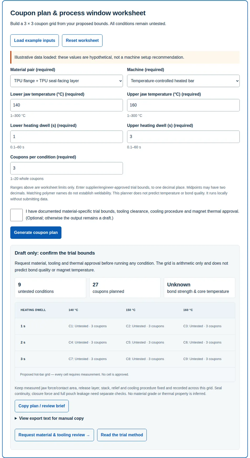
A / Matched TPU trial draft
Assumptions: TPU flange and TPU-facing film; temperature-controlled hot bar; exact grades, tooling and thermal approval still unconfirmed.
Process: Load the hypothetical 140–160 °C and 1–3 s example with three coupons per cell.
Planning outcome: Nine untested combinations and 27 planned coupons. Status remains draft. Obtain documented bounds before using the machine; strength, leakage and core temperature remain unknown.
B / Silicone-coated pouch
Assumptions: Proposed TPU flange against an identified silicone coating; no qualified joining construction supplied.
Process: Select mixed polymers / silicone in the worksheet.
Planning outcome: Grid is held. Export a review brief and request an alternative carrier or qualified bonding route. Increasing temperature is not a substitute for compatibility evidence.
C / Transfer to an impulse machine
Assumptions: An existing hot-bar lab plan; intended production equipment is controlled by impulse time / power.
Process: Change the machine selection to impulse.
Planning outcome: Grid is held for controller-profile review. Capture the temperature and cooling trace, then plan a separate transfer study. No equivalence or production yield is asserted.
10 / Controlled transfer
Release a documented process only after assembly evidence
Our recommended trial handoff contains the approved material and drawing revisions, equipment identification, measured control variables, coupon results and unresolved deviations. Assign a responsible engineer to the acceptance decision. Repeat the relevant checks on production tooling and define revalidation triggers such as a coating, magnet construction, release film or machine change.
The lab-to-line gap is explicit in F2029. Reference: S1. Actual sampling frequencies, magnetic retention tolerances and leak limits must come from your quality plan; no universal lot-release percentages are prescribed here.
11 / Practical questions
Questions before heat sealing closure strips
Materials and equipment
Can every magnetic closure strip be heat sealed?
No. Identify a weldable attachment flange and its seal-facing material. A textile carrier, encapsulation layer or product-family label alone is insufficient. Request the actual construction drawing and material identification.
Does TPU-to-TPU mean the pair will weld?
It is a candidate for investigation only. Grade, additives, coatings and the complete laminate still require supplier evidence and trials. The worksheet does not establish chemical compatibility.
Can I apply the grid to an impulse sealer?
The temperature grid is for a temperature-controlled hot bar. An impulse controller may use power or time settings with a varying temperature profile. The tool holds the grid and prepares a review brief until that profile is addressed.
Can silicone-coated fabric use the same process?
Do not transfer the direct thermoplastic sealing plan without a separately qualified joining route. Ask for a mechanically attached carrier or a material-specific bonding evaluation. Primer chemistry and curing settings are outside this worksheet.
Numbers and interpretation
Where do the example settings come from?
They are hypothetical arithmetic inputs: 140–160 °C, 1–3 s and three coupons per condition. They demonstrate a nine-condition matrix, not a tested recipe, recommended window or product capability.
Does the tool predict interface or magnet temperature?
No. Jaw temperature alone does not define either temperature. Obtain a material-specific thermal limit and measure an instrumented assembly under the intended cycle.
Is a pneumatic gauge reading the seal pressure?
No. Gauge pressure needs actuator and mechanism information to estimate jaw force, and contact pressure also needs the actual loaded area. Record calibrated force and area; do not compare air-line bar across machines as equivalent contact pressure.
Does a prepared plan mean I can release production?
No. Even a plan with documented bounds has untested cells. Trial execution, acceptance decisions and transfer to production tooling remain separate steps. The export states these limits.
Testing and next steps
Is there a universal 35 N/25 mm pass threshold?
This guide defines none. Agree acceptance criteria for the application, material, specimen width, conditioning and method before testing. A test-method reference is not a universal product acceptance requirement.
Does substrate tear prove a watertight pouch?
No. Record the force and failure mode, then test seal continuity and the complete assembly against its separate leak or ingress requirement. A strong coupon does not inspect corners or the reclosable opening.
What if no qualified trial bounds exist?
Leave the worksheet blank or create a draft for discussion. Send layer identification, stack dimensions, machine controls and the intended application to engineering. Do not treat the illustrative example as the missing supplier data.
What should accompany a sample request?
Include the proposed material pair, material lots if available, flange drawing, jaw length, machine type, measured pressure basis, cooling method and the acceptance questions. Attach the copied plan and list every unresolved item.
12 / Evidence ledger
Sources, dates and limits of this guide
Public source scopes reviewed on 2026-10-29. These links support method selection and evidence boundaries. They do not supply assembly-specific settings. Obtain the full applicable edition for laboratory execution and confirm the edition agreed with your customer. MagZipStrip engineering owns source review at least every six months (next by April 29, 2027), and after a material, method or equipment change. No paid standard text or complete procedure is reproduced here.
- S1: ASTM F2029-16(2021): laboratory heat-seal preparation
Public scope: hot-bar / impulse laboratory preparation. Production equipment validation and seal continuity are outside its scope.
- S2: ASTM F88/F88M-23: seal strength of flexible barrier materials
Public scope: seal separation force and failure mode. Fixture technique affects comparisons; this is not an assembly leak rating.
- S3: ASTM D1876-08(2023): adhesive T-peel resistance
Public scope: relative peel resistance of adhesive bonds between flexible adherends. Use only when its geometry and scope fit the agreed investigation.
- S4: K&J Magnetics: Temperature and Neodymium Magnets
Manufacturer explanation, updated January 2, 2025: thermal behavior depends on grade, shape and magnetic circuit. It does not qualify a MagZipStrip assembly.
For product-family scope, see the weldable magnetic closure strip hub. For this trial, send the worksheet and unresolved evidence to MagZipStrip engineering.